Poseidon Mk. 1

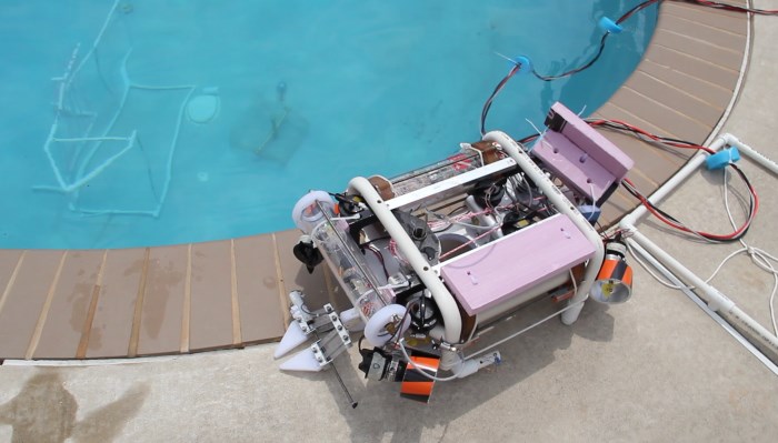
We used PVC for the frame of Poseidon Mk. 1 because it is cheap and easy to work with. We chose this shape because it had superior stability, tool mounting options, and a better ability to support our vectored thruster arrangement. Vectored thrusters are propellers arranged at the four corners of the ROV and angled at 45 degrees. This arrangement allowed maximum maneuverability using fewer thrusters.

The electronics, including the camera (fig. 1), were encased in a custom-made waterproof pressure housing in the center of the ROV (fig. 2).

ROVs use a tether to receive power and to communicate with the surface. On the surface, we had a laptop that ran the main program running the ROV. We used an Xbox 360 controller to pilot the ROV, because it allowed great control and several input options.

After the Regional competition, we added the rotating tool mount (RTM) under the ROV, which allowed the use of up to four different tools, despite only having one camera. One of the tools used was a manipulator (fig. 3).

Poseidon Mk. 2

Our second year, we decided to do a major design overhaul. We experienced several problems with Mk. 1, including (but not limited to) trouble with waterproofing, slow movement, and bulky stature. We switched to a frame made of cutting board (bought from Chef Depot), because it was sturdy, easy to machine, and light. This allowed for a more compact and hyrdrodynamic ROV, while still providing great stability and control (fig. 4).

We opted to have two smaller pressure housings, because they provided better stability and because we would be able to access the electronics inside more easily (fig. 5). One pressure housing contained the main processing chip and the camera, while the other pressure housing contained our custom-built motor controllers, which control the thrusters and the manipulator.

The waterproof seal on the pressure housings was achieved using two o-rings sandwiched between the ends of the housings and a Lexan disc. Waterproof connectors allowed wires to pass through that disc. You can see the electronics placed inside one of the pressure housing in fig. 6.

We did not incorporate an RTM into Poseidon Mk. 2, because we only needed a manipulator to complete that year's mission tasks.

Poseidon Mk. 3

The previous year, the front of the ROV was one of the pressure housings, which was located on the longer side of the ROV. For Poseidon Mk. 3, we reoriented the main design for better hydrodynamics. We added a small pressure housing for the camera along the short side of ROV. We added two vertical thrusters and upgraded some of the rest, so that they had more power.

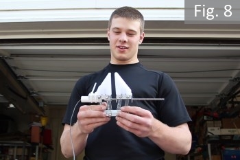
We included an RTM in the main design, which provided access to the manipulator and two other tools. The manipulator was redesigned (fig. 7 and fig. 8), due to disappointing results with the previous design. The new manipulator worked flawlessly.

Although it may seem like not much was added or changed between Mk. 2 and Mk. 3, that is not the case. Most of the changes were small or very technical, which we do not feel the need to describe at this time. For more in-depth information, refer to the 2012 Technical Report, the 2013 Technical Report, and the 2014 Technical Report.